|
of the RB-29 in the Korean War from An Aerial Photographer’s Point of View by Wayland Mayo |
||||||
|
MISSION PLANNING AND CALCULATIONS MISSION PLANNING The crew is notified by Bomber Command exactly what areas need to be photographed, and the required scale of the photos. The navigator and photographer then must work together to determine which cameras to install, and calculate the altitudes required to produce the required scale. For example: to produce a photo at a scale of one inch equals 1000 feet with the six inch camera you would multiply the focal length times the scale. In this case the flight height would be 6000 feet. That is AGL, or above ground level. We have to add the datum, or average ground elevation. Conversely to determine the scale we would divide the focal length into the altitude. An altitude of 6000’ with a six inch camera would produce a one inch equals 1000’ scale. MORE MATHEMATICAL CALCULATIONS Exposure stations or distance on the ground between exposures to produce the required 60 per cent forward overlap can be calculated by multiplying 3.6 times the scale of photography. For example: With photography at a scale of one inch equals 1000 feet the camera would have to be tripped every 3600 feet. This calculation is necessary to figure in advance how many photos it will take to cover a flight line. If the flight line is 30 miles long at a scale of one inch equals 400 feet, 3.6 times 400 equals an exposure every 1440 feet. 30 miles equals 158,400 feet. Divide this by 1440 and you will need 110 exposures to cover that flight line. The negative is 9 inches wide, so at a scale of one inch equals 400 feet coverage across the flight line would be 3600 feet. We now know how to figure altitude, how many negatives required to cover the flight line, and how to calculate scale. Now we need to know how far apart the flight lines must be to produce a 30 per cent sidelap. Flight line separation can be figured by multiplying 6.3 times the scale. At a scale of one inch equals 1000 feet, to produce parallel flight lines with a 30 per cent sidelap the flight lines would be flown 6300 feet apart. Now we have the required 60% overlap and 30% sidelap. |
||||||
 |
||||||
|
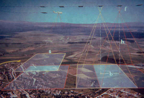
are interested in details. The “f ” = Camera focal length Every stereoplotter has a “C{ FACTOR , which is the altitude the aircraft can fly and produce a negative with which the stereoplotter can produce a one foot contour map accurate to three inches vertically. A first order plotter will usually have a “C” FACTOR of 2400, which means the aircraft can produce a negative at a scale of 1 = 400' from which the plotter operator using depth perception and the “floating dot principal” can produce a first order map meeting National Map Standards. The plotter can plot what is called the “neat” model, which is the stereoscopic area between the principal points. This and the “C” FACTOR are controlled by the base height ratio, which is the distance between exposure stations and the flight height. The longer the base in relationship to the height the more accuracy can be obtained from the photography. |
||||||
|
End of Chapter 04 — Go to Chapter 05 Chapter — 01 — 02 — 03 — 04 — 05 Introduction — Table of Contents Home - Contact Us - Cold War Hist. - 91st SRS Hist. - Stardust 40 Mission Story |
||||||