|
of the RB-29 in the Korean War from An Aerial Photographer’s Point of View by Wayland Mayo |
|||||||||||||||
|
|
|||||||||||||||
|
Wayland’s The B-29, with it’s awesome destructive power, is legendary. We all consider the atomic drops on Hiroshima and Nagasaki as being the most devastating of all. However, the incendiary attacks on Tokyo, Nagoya, and Osaka actually caused greater damage than both atomic attacks. The M-69, M-47, and M-15 magnesium thermite incendiaries would have eventually leveled every city in Japan. Targets in Korea were far more difficult to hit due to the dispersion of enemy troops. Bridges were difficult to hit, with most bomb runs straddling the bridge. Airfields that were hit one day were repaired for use the next day. We did not possess the “smart bomb” that is so effective today. So we pretty well know about the B-29 accomplishments, but what about the RB-29. This story contains my personal observation and evaluation of the RB-29. We will begin with a look at production problems with the B-29, along with some technical specifications. Then we will take a look at the purpose of the RB, and the camera configuration. B-29 PRODUCTION PROBLEMS |
|||||||||||||||
|
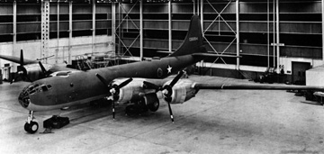
The first production B-29 rolled off the assembly line at the Boeing plant in Wichita in 1943. Numerous problems almost kept it from ever being produced. The R-3350 engine malfunctioned repeatedly, mostly from overheating and fires. The overheating was occurring around the exhaust valves of the rear row of the 18 cylinder engine, causing complete engine failure.
By installing 14 new engine baffles, cooling air was directed on the rear exhaust valves. The fixed cowl flaps on top were made operable. Also oil was redirected to obtain a better flow to the valves that were overheating. So the B-29 was born with a multitude of problems , and many accidents occurred. The R-3350 was always a “leaker”. Preflight procedures during pressure checks almost always found an oil leak. |
|||||||||||||||
 |
|||||||||||||||
|
Ctsy Aero Publishers, Inc. (Boeing 62450/BW11392) |
|||||||||||||||
 |
|||||||||||||||
|
|
|||||||||||||||
|
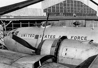
The pressurization system was unique in that the front compartment and the rear compartment were both pressurized. Since the two compartments were separated |
|||||||||||||||
|
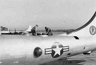
The first B-29’s produced had twelve 50 caliber machine guns, plus a 20 mm cannon mounted in the tail. The cannon was later discontinued and only a few were produced. The gunnery system had a central fire control which used an automatic computer to correct for airspeed, range, altitude, and temperature. It was sophisticated, even by todays standards. This system allowed any gunner, except the tail gunner, to take over more than one power driven turret. Gunners did not have actual contact with the guns, as they were fired from remote stations using a sighting device. |
|||||||||||||||
 |
|||||||||||||||
|
|
|||||||||||||||
 |
|||||||||||||||
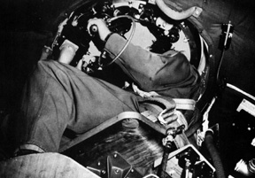
| The head gunner, or central fire control man, sat in an elevated revolving “barber chair”. He could look out the top of the aircraft and had primary control over the upper forward and upper aft turrets. The gunners compartment was just aft of the rear bomb bay. The left and right gunners looked out a Plexiglas dome on each side of the aircraft. The CFC man sat in the middle of the section and also had a dome on top of the aircraft. The sighting device was unique in that the gunner did not have to take a “lead” on the target. |
|||||||||||||||
|
Ctsy. Aero Publishers, Inc. |
|||||||||||||||
| Regardless of speed or direction of flight the sight automatically calculated the lead, so the gunner could keep his sight fixed on the target at all times. Beside being gunners, they also acted as scanners, relaying information to the pilot as to the position of the gear, flaps, oil leaks, or any other problems. End of Chapter 01 — Go to Chapter 02 Chapter — 01 — 02 — 03 — 04 — 05 Introduction — Table of Contents Home - Contact Us - Cold War Hist. - 91st SRS Hist. - Stardust 40 Mission Story |
|||||||||||||||